2. 玉林师范学院物理科学与工程技术学院,广西玉林 537000
2. Institute of Physics Science and Engineering Technology, Yulin Normal University, Yulin, Guangxi, 537000, China
【研究意义】工程使用的金属材料一般是由若干晶粒组成的多晶体,晶粒与晶粒之间由于取向不同,在二晶交界处形成晶界。晶界中包含很多缺陷结构,如位错,空位,间隙原子等。材料在加工过程中受到不同的加载作用,如挤压、拉伸,以及温度的影响等,都直接引起材料内部微结构的变化。然而, 晶粒内部是如何变化的, 这一问题一直在困扰着人们,也是材料科学研究领域的难点和重点[1-3]。【前人研究进展】在过去,由于实际中多晶材料变形演化的复杂性,使用实验方法直接进行原位观测微观组织变化是相当困难的。随着如今计算机技术的飞速发展,计算机仿真技术在很大程度上解决了上述问题。【本研究切入点】晶体相场(PFC)法[4-5]基于经典密度泛函同时结合了传统相场方法,用局域密度场表示序参量,成功地实现模拟材料微观组织结构的实时演化。经过近年来的发展,PFC方法在模拟晶体断裂、相结构转变、纳米晶粒长大、位错滑移与攀移等方面都有许多的应用[6-14]。【拟解决的问题】采用PFC法模拟纯物质的纳米多晶结构,研究多晶材料在应力作用下缺陷运动情况,探究晶界位错缺陷的运动规律,揭示纳米多晶体材料塑性变形的微观细节和机理。
1 PFC模型PFC模型能够揭示晶体点阵周期结构特性以及空间分辨尺度为原子尺度,时间尺度为扩散时间尺度下的纳微结构演化[10-11]。对于固态晶体材料,其原子的位置呈规则周期性排列,通过引入周期性相场变量ρ(r),其空间分布的极大值位置对应于原子点阵的位置;对于均匀相(液相等)中的原子密度分布为均匀分布,其值为常量。用周期原子密度函数ρ(r)作为相场变量,要符合上述两方面的要求,其表达式可以写成[4-5]
| $ \rho \left( r \right) = \sum\limits_{n, m} {{a_{n, m}}{e^{iG \times r}}} + {\rho _0}, $ | (1) |
式中,等号右边第1项反映的是晶格原子的周期排列结构特征,其中G为倒格子矢量,r为空间坐标矢量;第2项反映的是均匀相(如液相)等的原子密度均匀分布。此时,系统无量纲的自由能函数可以写成[4-5]
| $ F = \int {\left\{ {\frac{\rho }{2}\left[{\gamma + {{\left( {1 + {\nabla ^2}} \right)}^2}} \right]\rho + \frac{{{\rho ^4}}}{4}{\rm{d}}{r^3}} \right.}, $ | (2) |
式中,ε为与温度有关的参数;∇2为拉普拉斯算符。
在单模近似下,由二维体系自由能取极小值,可以求得公式(2)的晶体相的一个稳定特解为[4-5]
| $ \begin{array}{l} \rho \left( r \right) = A\left[{\cos \left( {qx} \right)\cos \left( {\frac{{qy}}{{\sqrt 3 }}} \right)-} \right.\\ \left. {\frac{1}{2}\cos \left( {\frac{{2qy}}{{\sqrt 3 }}} \right)} \right] + {\rho _0}, \end{array} $ | (3) |
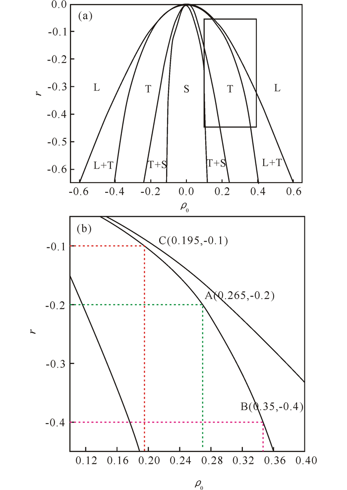
式中,
|
L为液相、T为六角相、S为条状相;(b)为参数选取,即(a)的方形区域放大图 L is liquid phase, T is hexagonal phase, S is stripe phase; (b) is parameter selection, i.e.magnified image of box in the (a) 图 1 二维PFC模型相图[4-5] Fig.1 Phase diagram of 2D PFC model[4-5] |
采用保守场Cahn-Hilliard动力学方程[4-5]描述原子密度随时间的演化。该方程具体如下:
| $ \frac{{\partial \rho }}{{\partial t}} = {\nabla ^2}\frac{{\delta F}}{{\delta \rho }} = {\nabla ^2}\left\{ {{\rho ^3} + \left[{\gamma + {{\left( {1 + {\nabla ^2}} \right)}^2}} \right]\rho } \right\}, $ | (4) |
式中,t为时间变量。对无量纲动力学演化方程(4),采用半隐式傅里叶伪谱方法求解,其中的时间偏导数用欧拉迭代法处理,详细的计算步骤可见文献[15-17]。
3 样品设置及参数选取采用PFC法研究面心立方结构[111]面的二维晶体结构,设置样品的空间尺寸为Lx×Ly=1024Δx×1024Δy,空间步长为Δx=Δy=π/4,样品的上下左右边界均采用周期性边界条件。在样品弛豫和加应力演化过程中,时间步长为Δt=0.5。
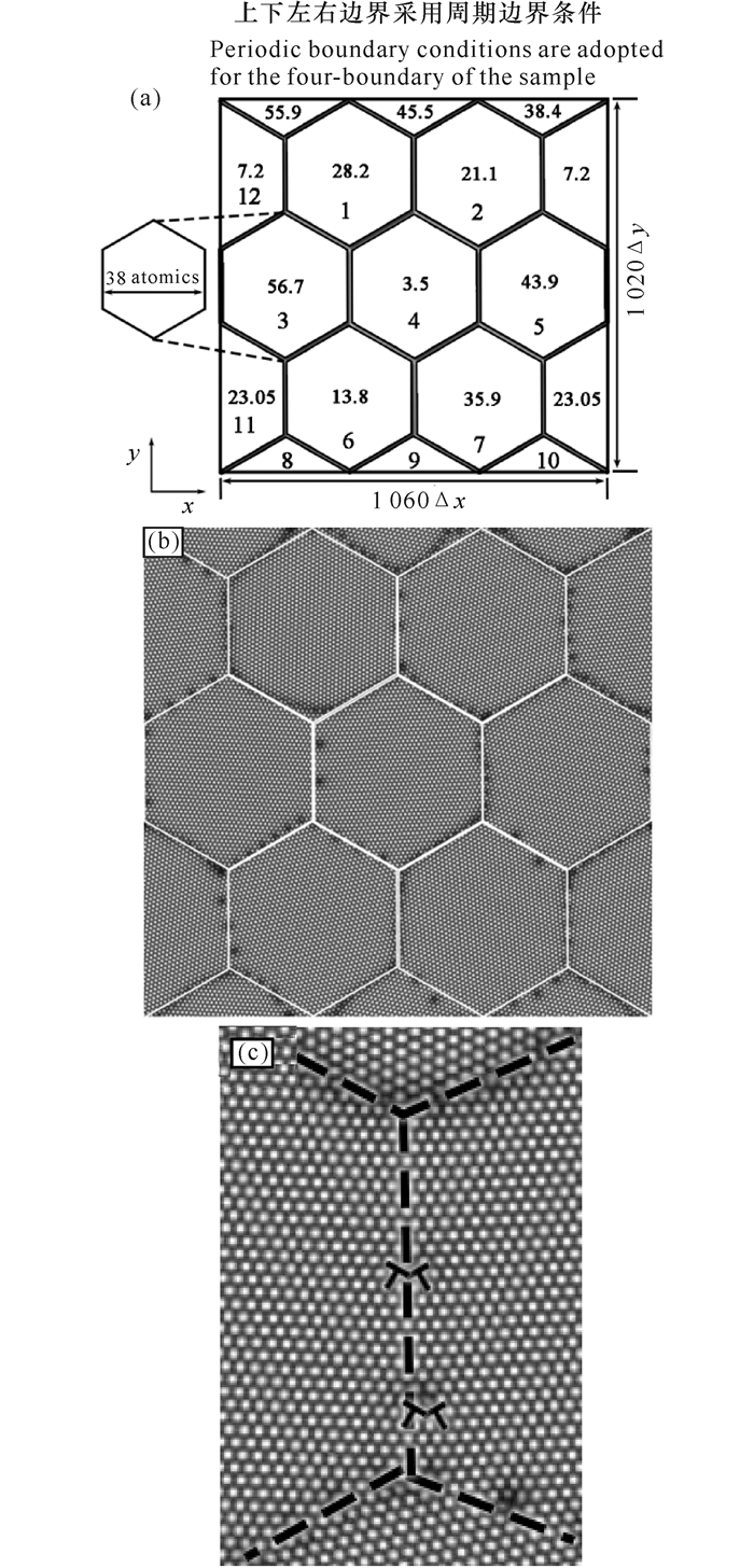
依据图 1的相图,选择模拟参数在六角相(T相)范围,靠近与液相共存的区域,这是为了保证体系处于六角相的同时,液相也能稳定存在。样品制备选取温度r=-0.2,平均密度ρ0=0.265,在y方向加载压应变,x方向加载拉应变。本研究中,模拟实验样品设置为12个六角晶粒,每个晶粒都有自己的取向(图 2a)。经过100 000步的时间步数的弛豫,消除内应力,使得样品晶界结构与内部能量稳定下来,得到了如图 2b的结果。从结果上来看,得到的稳定晶界与初始设置的边界较为一致。采用等面积法模拟对样品施加挤压与拉伸加载。如图 2c给出了三叉晶界的位错结构。
|
图 2 (a) 样品的晶粒和晶界结构参数设计, (b)制作的模拟实验样品, (c)三叉晶界的位错结构 Fig.2 (a)The design of the structure parameter of the grain and grain boundary of sample, (b) The sample for simulation experiment, (c) The dislocation structure of the tri-grain boundary (GB) |
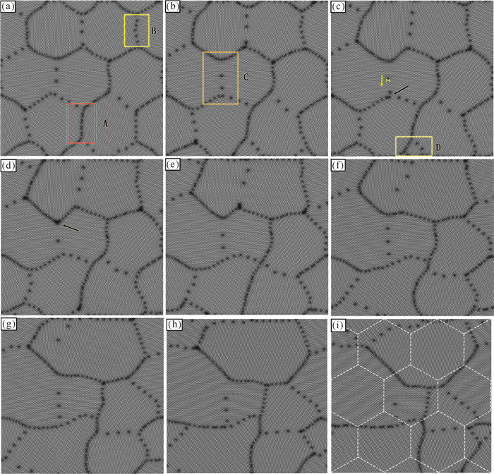
从图 3a~b可以看到,在应变ε < 0.02前,样品中的晶粒没有发生较大的变形,以位错沿着晶界运动为主。随着应变的增加(图 3c~i,ε>0.02),样品开始出现了晶粒旋转和晶粒吞并等现象。晶粒旋转主要发生在取向差较小的两晶粒之间(如图 3b中黄色方框所示),而晶粒吞并现象发生在大晶粒与小晶粒之间。此外,在变形的后期阶段(图 3e~i),进一步出现了晶界迁移,并且晶粒粗化加速,而晶界也变得平直化。位错与晶界的运动在变形过程中起到主导作用。
|
(a)ε=0;(b)ε=0.02;(c)ε=0.03;(d)ε=0.04;(e)ε=0.06;(f)ε=0.08;(g)ε=0.10;(h)ε=0.12;(i)ε=0.15 图 3 样品微结构的演化过程 Fig.3 Evolutionary process of microstructure in the sample |
在多晶体材料热处理过程中,从晶界的稳定角度分析,晶粒的生长有两种情况:弯曲的晶界势必会向着平直化方向发展;当晶粒边界数少于6时,其晶界必然向外突出。由于晶界曲率的存在,晶界向着曲率中心迁移,这就导致了晶粒缩小;相反,当晶粒晶界数大于6时,其晶界必然向内凹,由于晶界曲率的存在,晶界向着曲率中心迁移,这就导致了晶粒生长。以图 3中的晶粒4为例, 与图 2a的晶粒2对照,可见晶粒4的边界数从开始的6变为5,最后变为4,整个过程晶粒4的尺度不断减小。
图 3a中A和B方框表示受到应变作用,大角度非对称晶界与小角度对称晶界上的位错运动。图 3b中C框是一个三叉晶界。图 3c~d中的箭头显示三叉晶界正在接收和发射位错,而在这个过程中,还发生了小晶粒被周围大晶粒吞并的情况(图 3c中的D框),这些情况在下文会详细分析。
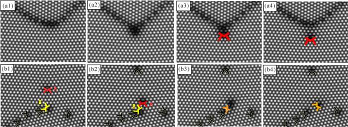
图 4a1~a4中显示在三叉晶发射位错之前,晶界会向前出现尖端,接着形成一个位错,然后位错发射离开晶界,之后晶界则恢复到原来的情况。在三叉晶界处,由于原子排列较为复杂,在应变的作用下,位错的运动往往会形成塞积,这时候如果没有较好地释放应变,容易形成晶格扭曲,导致三叉晶界发生开裂,形成空洞[2]。由图 4b1~b4可见,在晶界上的位错B其柏氏矢量与其它晶界运动过来的位错A的柏氏矢量存在一个夹角,因此,当位错A遇到晶界时,与位错B反应,生成一个新的位错。位错反应写成如下公式:
|
(a1) t=69 500;(a2) t=84 500;(a3) t=87 500;(a4) t=88 500;(b1) t=36 500;(b2) t=60 500;(b3) t=61 500;(b4) t=63 500 (a)三叉晶界发射位错; (b)三叉晶界吸收位错 (a)Emission dislocation in tri-GB junctions; (b)Absorption dislocation in tri-GB junctions 图 4 三叉晶界在纳米多晶材料变形过程中的演化 Fig.4 Evolution of the tri-GB of polycrystal materialis during the deformation |
| $ {B_A} + {B_B} = \left( {{b_1} + {b_2}} \right) + \left( {{b_3} + {b_4}} \right) = {b_1} + {b_4} = {B_C}, $ |
式中分量b2=-b3。说明晶界吸引位错的一个原因是外来位错与晶界上位错的柏氏矢量(或者其分量)相反。
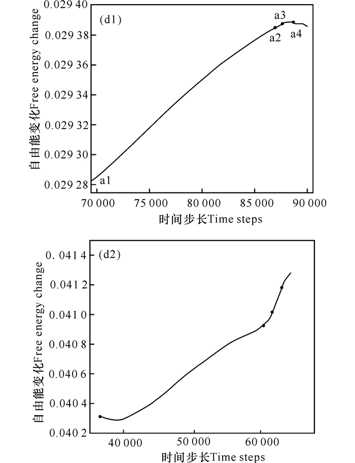
图 5d1展示了晶界发射位错的自由能变化,在释放位错的过程中,区域内自由能不断上升,直到位错发射出晶界(t=87 500),能量达到了顶峰,这时候位错已经脱离了晶界,区域内的原子排列畸变减小,晶界恢复稳定,能量开始下降。这表明释放位错有助于减少晶界表面能。图 5d2展示了晶界吸收位错的自由能变化过程,一般而言,晶界对位错存在吸引和排斥两种作用[18],这两种作用决定了晶界对位错的行为。由图 5d2可见,整个过程的能量呈上升趋势,特别是晶界吸收了位错之后,能量上升速度加快。这是由于晶界吸收了位错,增加了晶界表面能。
|
(d1)晶界发射位错; (d2)晶界吸收位错 (d1) Emission dislocation of the GB; (d2) Absorpsion dislocation of the GB 图 5 发射位错与吸收位错能量变化 Fig.5 Energy change of emission dislocation and absorpsion dislocation of the GB |
采用PFC模型研究纯物质多晶体材料变形过程内部结构演化过程,通过对模拟结果的分析得到如下结果:采用PFC模拟多晶体塑性变形,在外加双轴动态加载作用下,当应变较小时,样品中的晶粒没有发生较大的变形,以位错沿着晶界运动为主。随着应变的增加,观察到晶粒旋转、晶粒吞并、大小角晶界迁移运动等现象。晶界释放位错有助于减少晶界表面能;吸收位错则增加了晶界表面能。这些现象在其他的模拟方法,如分子动力学方法中也观察到了,表明PFC方法可以有效模拟多晶体材料塑性变形过程。
| [1] |
SHEIN I R, KIĬKO V S, MAKURIN Y N, et al. Elastic parameters of single-crystal and polycrystalline wurtzite-like oxides BeO and ZnO:Ab initio calculations[J]. Physics of the Solid State, 2007, 49(6): 1067-1073. DOI:10.1134/S106378340706008X |
| [2] |
ZHU L F, FRIÁK M, LYMPERAKIS L, et al. Ab initio study of single-crystalline and polycrystalline elastic properties of Mg-substituted calcite crystals[J]. Journal of the Mechanical Behavior of Biomedical MAterials, 2013, 20: 296-304. DOI:10.1016/j.jmbbm.2013.01.030 |
| [3] |
邓芊芊, 胡绪志, 黄礼琳, 等. 条状晶位错运动的晶体相场模拟[J]. 广西科学院学报, 2017, 33(4): 223-227. DENG Q Q, HU X Z, HUANG L L, et al. Phase field crystal study on dislocations movement in strip grain[J]. Journal of Guangxi Academy of Sciences, 2017, 33(4): 223-227. |
| [4] |
ELDER K R, KATAKOWSKI M, HAATAJA M, et al. Modeling elasticity in crystal growth[J]. Physical Review Letters, 2002, 88(24): 245701. DOI:10.1103/PhysRevLett.88.245701 |
| [5] |
ELDER K R, GRANT M. Modeling elastic and plastic deformations in nonequilibrium processing using phase field crystals[J]. Phys Rev E Stat Nonlin Soft Matter Phys, 2004, 70(1): 051605. |
| [6] |
高英俊, 杨瑞琳, 王玉玲, 等. 空位晶体相场模型模拟二维晶体相形貌图[J]. 广西科学, 2015, 2015, 22(5): 485-491. GAO Y J, YANG R L, WANG Y L, et al. Phase field model simulation of bumps and holes pattern of two dimension crystals[J]. Guangxi Sciences, 2015, 2015, 22(5): 485-491. |
| [7] |
黄世叶, 李胜男, 胡绪志, 等. 晶界位错运动的空位晶体相场模拟[J]. 广西科学, 2016, 23(5): 459-464. HUANG S Y, LI S N, HU X Z, et al. Vacancy phase-field-crystal simulation of dislocation motion of grain boundary[J]. Guangxi Sciences, 2016, 23(5): 459-464. |
| [8] |
杨瑞琳, 刘瑶, 胡绪志, 等. 双位错滑移运动的晶体相场模拟[J]. 广西科学, 2016, 23(5): 443-447. YANG R L, LIU Y, HU X Z, et al. Phase-field-crystal simulation of double dislocation gliding[J]. Guangxi Sciences, 2016, 23(5): 443-447. |
| [9] |
黄礼琳, 邓芊芊, 卢昱江, 等. 缺陷预熔化现象的晶体相场模拟[J]. 广西科学院学报, 2017, 33(4): 234-239. HUANG L L, DENG Q Q, LU Y J, et al. Phase field crystal simulation of defect pre-melting phenomenon[J]. Journal of Guangxi Academy of Sciences, 2017, 33(4): 234-239. |
| [10] |
卢昱江, 孔令一, 邓芊芊, 等. 微裂纹起裂扩展机理的晶体相场模拟[J]. 广西科学院学报, 2017, 33(4): 240-245. LU Y J, KONG L Y, DENG Q Q, et al. Phase field crystal simulation of nucleation and propagation of micro-cracks[J]. Journal of Guangxi Academy of Sciences, 2017, 33(4): 240-245. |
| [11] |
高英俊, 罗志荣, 邓芊芊, 等. 韧性材料的微裂纹扩展与分叉的晶体相场模拟[J]. 计算物理, 2014, 31(4): 471-478. GAO Y J, LUO Z R, DENG Q Q, et al. Phase-field-crystal modeling of microcrack propagation and branching in ductile materials[J]. Chinese Journal of Computational Physics, 2014, 31(4): 471-478. |
| [12] |
HIROUCHI T, TAKAKI T, TOMITA Y. Developme-nt of numerical scheme for phase field crystal deformation simulation[J]. Computational Materials Science, 2009, 44(4): 1192-1197. DOI:10.1016/j.commatsci.2008.08.001 |
| [13] |
GREENWOOD M, PROVATAS N, ROTTLER J. Free energy functionals for efficient phase field crystal modeling of structural phase transformations[J]. Phys Rev Lett, 2010, 105(4): 045702. DOI:10.1103/PhysRevLett.105.045702 |
| [14] |
CONRAD H, NARAYAN J, JUNG K. Grain size softening in nanocrystalline TiN[J]. International Journal of Refractory Metals & Hard Materials, 2005, 23(4): 301-305. |
| [15] |
BERRY J, PROVATAS N, ROTTLER J, et al. Defect stability in phase-field crystal models:Stacking faults and partial dislocations[J]. Physical Review B, 2012, 86(22): 224112. DOI:10.1103/PhysRevB.86.224112 |
| [16] |
BERRY J, ELDER K R, GRANT M. Melting at dislocations and grain boundaries:A phase field crystal study[J]. Physical Review B, 2008, 77(22): 224114. DOI:10.1103/PhysRevB.77.224114 |
| [17] |
孔令一, 卢昱江, 邓芊芊, 等. 二维大取向角对晶界湮没过程的晶体相场模拟[J]. 广西科学院学报, 2017, 33(4): 228-233. KONG L Y, LU Y J, DENG Q Q, et al. Phase field crystal simulation of grain boundary annihilation with two dimensional large orientation angle[J]. Journal of Guangxi Academy of Sciences, 2017, 33(4): 228-233. |
| [18] |
ROTH C C, MOHR D. Effect of strain rate on ductile fracture initiation in advanced high strength steel sheets:Experiments and modeling[J]. International Journal of Plasticity, 2014, 56(4): 19-44. |
 2017, Vol. 24


